October 2026
When’s good kite weather?
An ambient kite that flies according to live wind speeds at Crissy Field in San Francisco.

As part of my master’s coursework, I was tasked to create an ambient display that takes in API data. As someone who doesn’t have a kite but loves to watch people fly theirs, I decided to create a cam-driven automaton to simulate a kite flying, and answer the question of “When’s good kite weather?”
Overview
A kite that knows when it’s a good day to fly.
I found a reference by stoccafisso_design ↗ where a row of cams lifts a ribbon of followers into a wave. The reference was animating (presumably) the young lady in ‘Brave’, but the design translated directly to my goals.
So my kite reads the wind at Crissy Field in San Francisco, and answers one question from across the room: is it a good day to fly a kite?

Turning live wind into three moods.
Every minute, the kite checks the real wind sensor at Fort Point, NOAA station 9414290 by the Golden Gate. If that reading fails or is more than 30 minutes old, it falls back to Open-Meteo’s weather model. If both are down for half an hour, the kite rests.
The key was designing states, not just scaling the motor’s speed with the wind. Most kites need around 5 to 25 mph, so I sorted the wind into three moods:
| Mood | Wind | What the kite does |
|---|---|---|
| Too calm | Under 8 mph | Rests. The motor stops. |
| Good | 8 to 20 mph | Flies with a gentle bob, a bit livelier as the wind picks up. |
| Too strong | Over 20 mph, or gusts of 25+ | Thrashes in fast, uneven bursts, building up over four seconds. |
Two details keep it readable. The motor always eases between speeds instead of snapping. And each line has 1 mph of stickiness, so when the wind hovers right at 8 mph, the kite doesn’t flicker between resting and flying.
Powering it from the wall.
I wanted the kite to live on a shelf as a permanent piece, so it runs from a USB-C wall adapter: an ESP32 Feather for Wi-Fi, and a continuous servo for the camshaft. A large capacitor across the servo’s power keeps the board from browning out when the motor starts. (A 1 amp spike for a millisecond dips about 1 volt with 1000 µF, and only about 0.2 volts with the 4700 µF I used.)
The circuit was the easiest part of the whole project. I tested it on a breadboard, then soldered it onto a protoboard, red for power and black for ground, with heat-shrink on the capacitor to cover open wiring.


Testing the fit, then building the box.
Before cutting the real box, I measured my materials, cut test strips to find the right dowel and bearing fits, and made sample corners to test my brackets and screws. A cardboard box came next.
For the walls, I wanted a little peekaboo moment: frosted acrylic on the front and sides for a clean finish, and clearer acrylic on the back where the electronics live. Rather than measure every part, I dropped top-down photos of the electronics into my Illustrator file and cut around them, which gave me perfect holes.
The first box had issues. The file was so complicated that I gave some sides the wrong designs, and I’d drawn everything for 4.5 mm material when my plywood was closer to 3 mm, so the joints were loose. After a round of fixes, I moved the USB port from the side to the bottom and raised the back of the base by 35 mm, so the cable disappears when the piece is plugged in.


Designing the cams and followers.
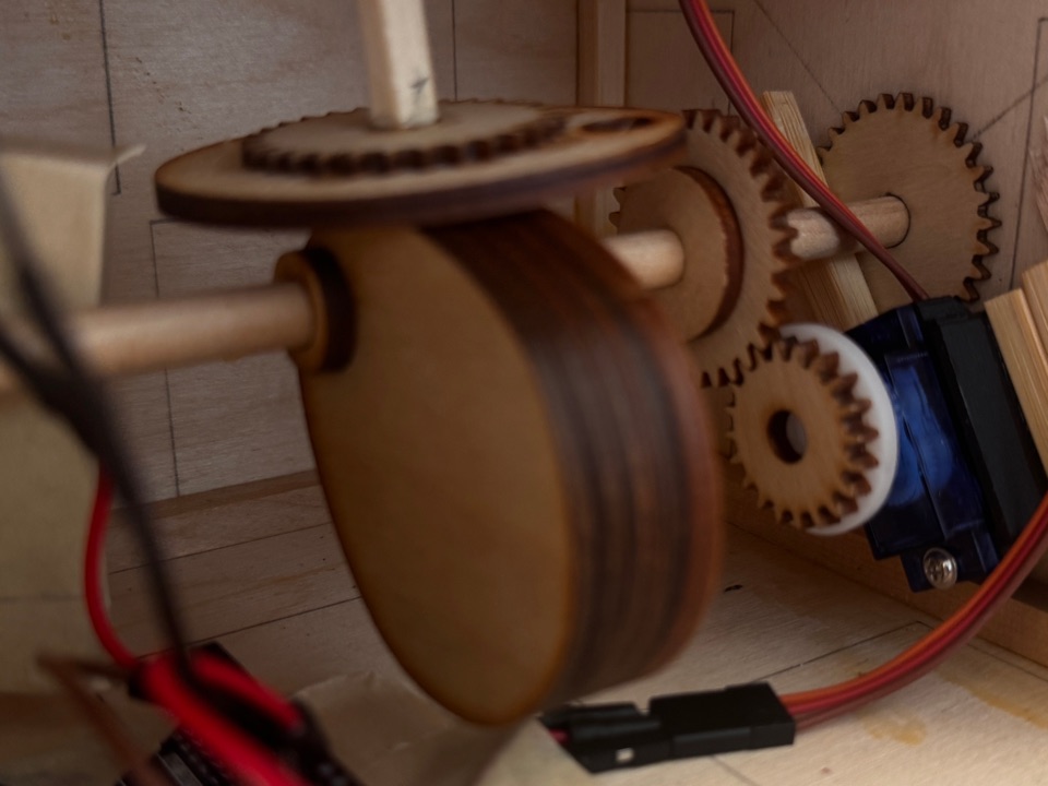
It’s hard to see in my reference, but each follower rides around a smaller circle. I sketched what that could look like and designed my first cams in varying sizes, so the kite would look like it was flying up a hill. Very thin columns to keep the cams apart turned out too fragile at under 1/16 inch, so I changed course.
For the hill, I sanded wooden circles from the scrap bin and glued two together into a taller dome. For the followers, the designs with several holes and a divot on top won: they let me adjust where each yarn sits and how high. Peeling the protective film off all those acrylic pieces took forever, until I started using a pokey stick. My fingernails were very happy.
To give the gears a hair’s width of play so they wouldn’t grind, I cut cardstock spacers to sit between them. And instead of cutting my wires shorter, I wound them around a pen.


Assembling the lid and dressing the hill.
I glued the lid’s layers with wood glue, pinning them through the holes I’d made for the mechanism so everything stayed aligned, then left it under weights. The top layers are plywood so fabric would bond to them, and the bottom layer is white acrylic, to hide the mess when you look up into the mechanism. The USB extender is epoxied between two acrylic layers, so the Feather simply plugs in and can come out for troubleshooting.
Then the fun part: wrapping the hill in fabric, threading yarns of different textures through the followers, and finishing with flower-shaped clothing grommets as nail heads, plus one turtle.


After crit, I changed the thrash from bursts in both directions to one direction only, to cut down on tangled yarns.
Details of the finished piece.


Learnings
What did I learn?
- 01
Prototype the fit before the part.
Scrap test holes, tolerance strips and a cardboard box saved me many recuts. The one time I skipped a check, designing for 4.5 mm material and cutting 3 mm plywood, I paid for it in loose joints.
- 02
Design for where it will live.
The kite runs from a wall plug with the cable hidden underneath, and its motion eases so you can read the mood from across a room.
How I used AI. I talked through my ideas with Cody rather than AI, and designed every part myself in Illustrator, with the gear and box generators he recommended. Claude helped me figure out which parts to buy and planned the kite’s wall-power circuit, and Copilot wrote most of the cat’s interaction code. That let me spend my time on the mechanisms.